In this tutorial you will learn:
In order to follow this tutorial please download the Rectangle.flowProject file and open it in FlowModeler. The Project contains a Line defined on a begin and end Point and a surface extruded from the Line.
FlowModeler offers different Modes it can operate in when a Project is loaded. These are:
Modes can be switched either in the Menubar with Project/Modes or with the Modes-Toolbar shown in the image below.
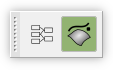
Please activate the Graph-Mode now.
After Graph-Mode has been activated you see that the Viewer changed its background color and nothing in the viewer.
Hint: if you find the background color too similar to the background color for the Geometry-Mode then you are able to change it in Preferences/Graph.
The next thing is too load some objects into the Graph. Therefore do a Right-Mouse-Button-Click on, Line.1 in the Tree and choose Show in Graph. The following item is now visible in the Viewer:

The item contains the following information:
If you do a Right-Mouse-Button-Click on the Graph-item the following Menu show up:
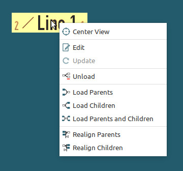
As the object has parents and a child choose Load Parents and Children from the Menu. This will load PointXYZ.1, PointXYZ.2 and Line.1/Edge.1 into the Graph. The objects show a connection between them if they are a direct parent and child. Graph items can be rearranged by selecting the item with the Left-Mouse-Button and moving it to a new position while the Mouse-Button is pressed.The view can be changed with the Mouse in the following ways:
Please load all remaining objects into the Graph. The view should look like this now:
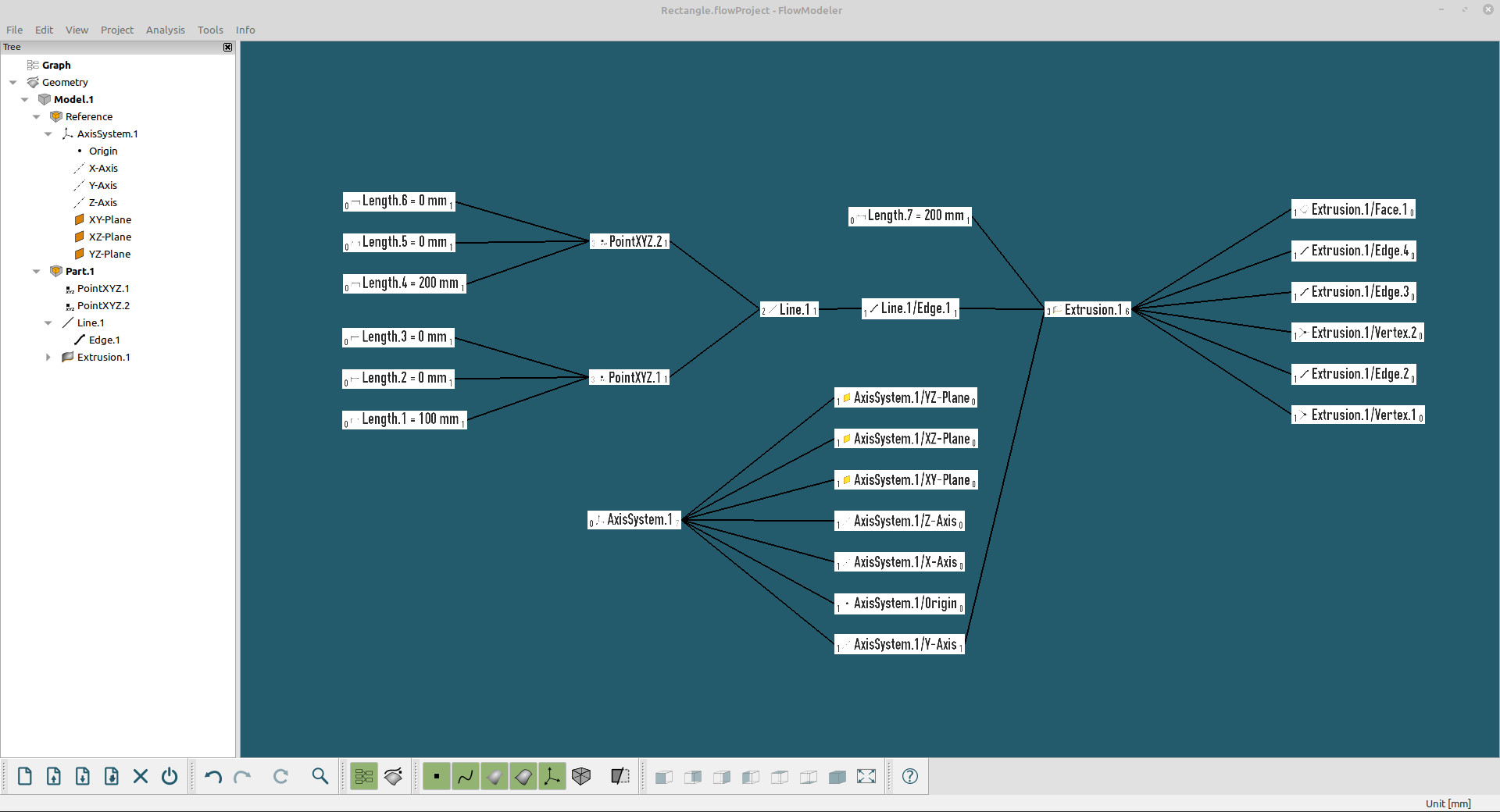
Objects can be in one of the following states:
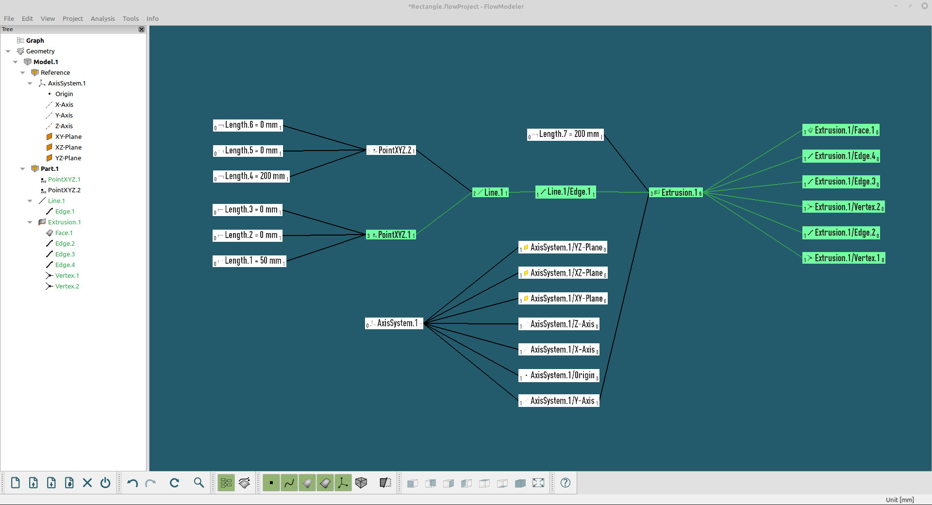
The different stated are communicated by the coloring in the Tree, the Graph and the 3D-Viewer. Outdated objects are shown in green, invalid objects in red. Valid objects will be shown in their default coloring.
To see the effects edit the value of Length.1. To do so you can either Double-Left-Mouse-Button-Click on the Length.1 item in the Graph or use the context menu of the item and choose Edit. Give Length.1 a new value of 50 and submit the Dialog with OK. The Graph now shows that all children of Length.1 are outdated.
 The objects can now be recomputed with the Update buttotn in the Edit-Toolbar or Edit/Update in the Menubar.
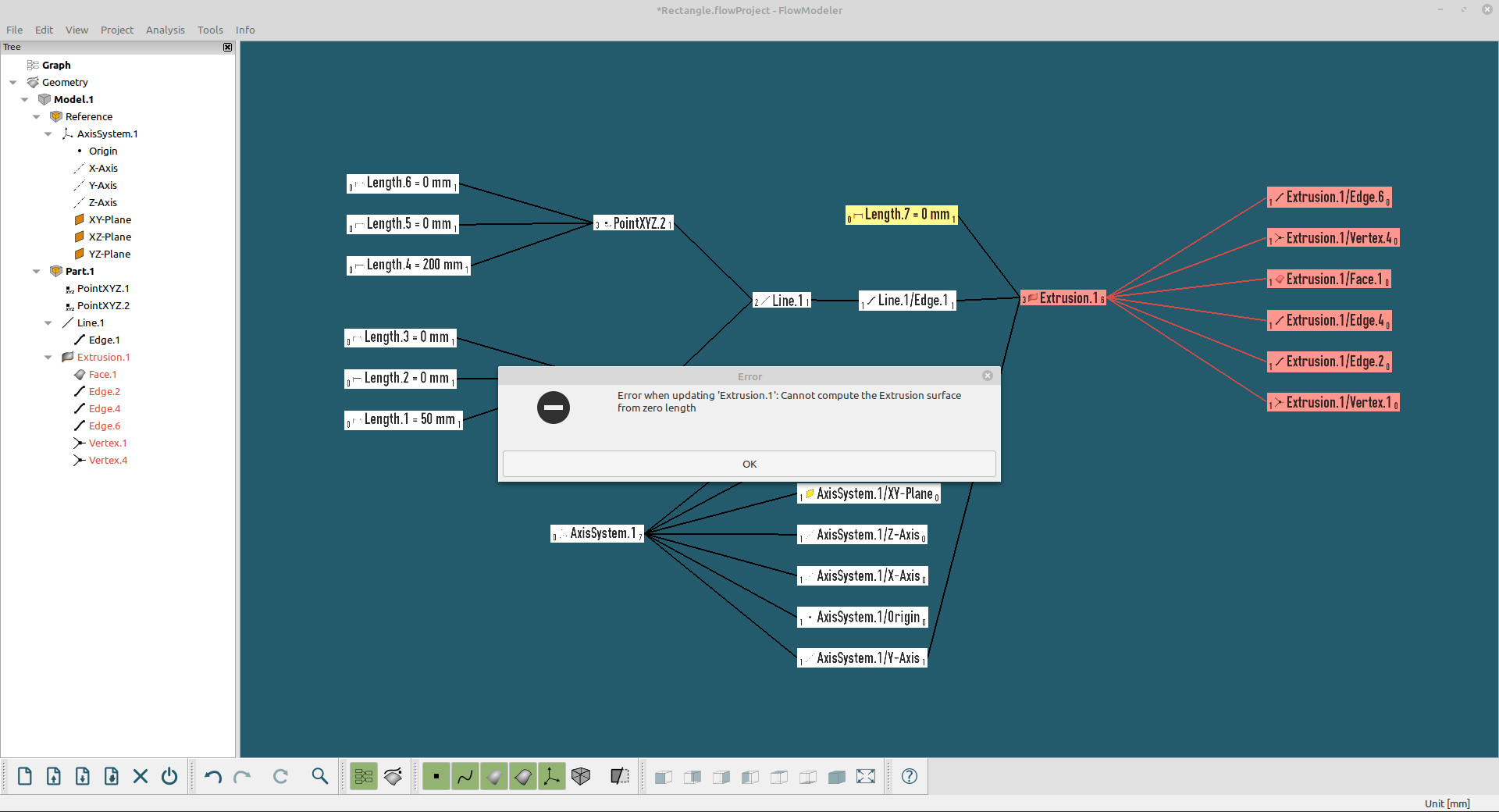
In order to provoke an error change the value of Lenth.7 to 0 so the computation of Extrusion.1 fails. When you now Update the Project an error message is displayed and Extrusion.1 and all its children are colored in red.
You may also switch to Geometry-Mode to see the effects there.
You are now able to manage object dependencies with the Graph-Mode and have been introduced to the different states objects can have.
Graph-Mode is designed to dynamically load and unload objects, that way only the objects of interest can be inspected.
Downloads